TL;DR
Key-locking threaded inserts (often called Keensert or keysert) reinforce damaged or soft-base threads like aluminum or low-carbon steel. Installation involves drilling, counterboring, tapping, insertion with controlled torque, and mechanically locking keys. Correct geometry control (tap class H3, depth tolerance ±0.2 mm) and key staking (0.5–1.5 J impact energy) are critical to achieving full load capacity without thread distortion.
Quick Installation Reference (Engineering Control Points)
| Stage | Key Parameter | Typical Value / Requirement |
|---|---|---|
| Counterbore | Angle | 90° ±0.5° |
| Tap class | Thread tolerance | H3 internal thread |
| Tap drill speed | Aluminum | 15–25 rpm |
| Tap drill speed | Steel | 8–12 rpm |
| Installation depth | Below surface | 0.25–0.76 mm |
| Preload torque (M6) | Insert driving torque | 2–3 N·m |
| Key staking energy | Impact per strike | 0.5–1.5 J |
| Key deformation | Final height reduction | ~1/3 key height |
Standards referenced in real production: ISO 965 (thread tolerance), ASME B1.1 (UN/metric thread system), IFI-124 / IFI-128 (key-lock insert geometry context), MS51830 (installation interface practices).
1. What a Key-Locking Insert Actually Does in Metal Repair
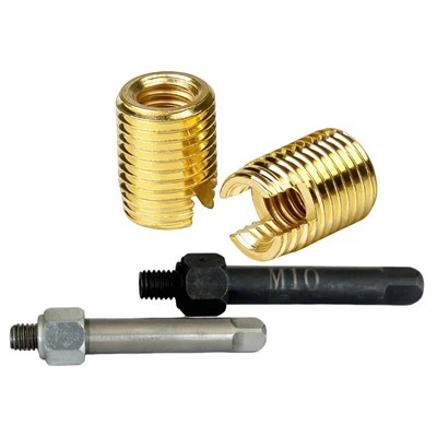
A key-locking insert is not a friction-based coil. It is a solid mechanical sleeve with external threads plus locking keys that physically deform into the parent material.
On aluminum 6061-T6 or cast housings, we typically see:
- Pull-out strength increase from ~2–3 kN (bare tapped hole)
- To 6–10 kN after proper insert installation
But only if the hole geometry is controlled. If your tap is off by 0.1–0.2 mm, the insert will feel "tight" during installation, then relax under load. That's a classic field failure we've seen on EV battery brackets.
2. Before You Start: Tools and Material Checks
Required tools (production-grade, not workshop assumptions)
- H3-class STI-style tap (matched to insert external thread system)
- Counterbore step drill with depth stop
- GO/NO-GO thread plug gauge (calibrated batch control)
- Torque driver (0.1 N·m resolution preferred)
- Copper or brass staking punch (HRB 65–80)
- MoS₂-based assembly lubricant
Base material conditions
We only recommend installation when:
- Aluminum hardness ≥ HRB 70 (or equivalent structural alloy condition)
- Minimum wall thickness ≥ 1.5 × insert outer diameter
- Hole cleanliness: no chips >0.1 mm remaining after tapping
In production, about 30% of "insert failure" complaints trace back to chip retention, not insert design.
3. Step-by-Step Installation Process (Controlled Method)
Step 1 - Drilling + Countersink (Combined Machining Step)

- Drill hole to insert specification (per catalog / STI size)
- Countersink immediately after drilling, no re-clamping
- Countersink angle: 90° ±0.5°
- Seat depth control: insert height + 0.2 mm
- Keep both operations in one setup to avoid misalignment
Note: Splitting drilling and countersinking often causes coaxial error (≈0.1 mm), which leads to insert tilt and uneven thread loading in service.
Step 2 - Precision tapping

- Tap class: H3
- Blind hole: spiral flute tap
- Through hole: straight flute tap
- Feed rate:
Steel: 8–12 rpm
Aluminum: 15–25 rpm
- Chip clearing: every 1–1.5 turns
A worn tap in 6061 can increase insertion torque by ~40%. We've measured this repeatedly on production lines.
Step 3 - Insert driving (pre-lock stage)

- Apply insert onto installation mandrel
- Drive torque (M6 reference): 2–3 N·m
- Alignment tolerance: ≤0.05 mm coaxial deviation
Insert top position:
- 0.25–0.76 mm below surface
Do not use direct impact tools here. If you do, thread galling starts at the first 2–3 turns and never fully recovers.
Step 4 - Key locking (mechanical anchoring)

This is the real strength mechanism.
- Tool: copper punch (HRB 65–80)
- Method: 3-point circumferential staking (120° spacing)
- Impact energy: 0.5–1.5 J per strike
- Key deformation target: ~1/3 key height
If keys are under-deformed, the insert will rotate under cyclic load. If over-deformed, you crack thin-wall aluminum. There is a narrow window here.
4. Torque & Assembly Behavior (What Actually Matters)
Once installed, torque performance depends more on base material than insert itself.
Typical observed behavior:
| Material | Thread retention improvement |
|---|---|
| 6061-T6 aluminum | +200–300% |
| Cast aluminum (A356) | +150–250% |
| Mild steel | +80–120% |
We ran cyclic tests (1000 cycles, 0.2–0.8× nominal load) where properly keyed inserts showed no measurable loosening. Improper key staking showed torque drop after ~200 cycles.
5. Common Failure Modes We See in Production
1. Oversized tap drill
Insert feels loose, then rotates under load.
2. Under-depth counterbore
Insert sits proud, bolt bottoming occurs before clamp load.
3. Chip contamination
Threads feel "gritty", torque spikes by 30–60%.
4. Improper key staking
Either:
- no deformation → rotation failure
- over-deformation → base material cracking
5. Misalignment (>0.05 mm)
Creates uneven flank loading, early fatigue cracking in aluminum housing.
6. Emergency Installation Method (Field Repair Scenario)
When no dedicated tooling exists:
- Machine guide sleeve: ID = insert OD + 0.02 mm
- Use hex nut as manual drive handle
- For key staking:
15° flat punch
3-stage circumferential pressing
Final key height tolerance: ≤0.1 mm variation around circumference
This is not aerospace-approved, but it works in maintenance environments where downtime matters more than certification.