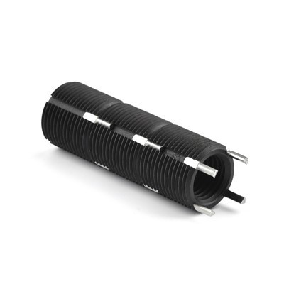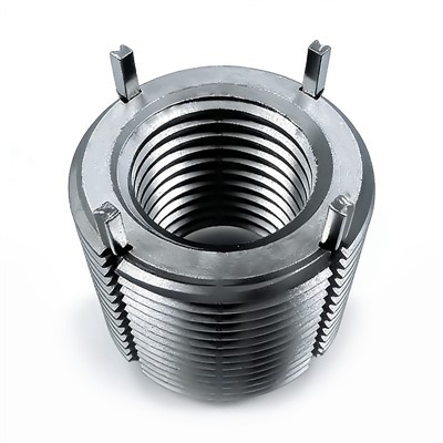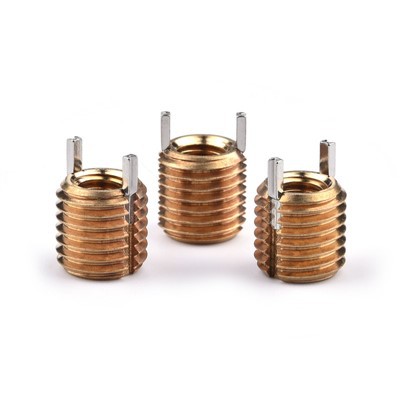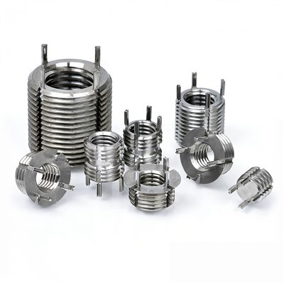


Keensert keyed threaded inserts from Nexlok Industrial Co., Ltd. provide durable, high-strength threads for aluminum, steel, and cast iron. Designed to prevent thread stripping, they withstand repeated installation and removal, making them ideal for aerospace, defense, and precision engineering applications. Perfect for new assemblies or repairing damaged threads.


Materials:
Keensert keyed threaded insert's materials:
- Carbon Steel
- Stainless Steel
- AISI 303
01
Classification:
By Thread Type:
- Metric
- UNC (Coarse)
- UNF (Fine)
02
By Insert Type:
- Miniature
- Lightweight (Thinwall)
- Heavy Duty
- Extra Heavy Duty
03
Surface Finishes:
- Silver Plated
- Blue Zinc Plating
- Cadmium Plated
- Dry Film Lubricant
04
Keensert Design Information
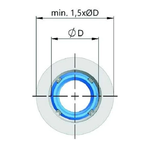
For KEENSERT inserts installed on the end face in round designs, the installation diameter should be at least 1.5 times the external thread diameter (ØD).

The edge or corner distance (e) for the thread inserts should be adapted to the specific application. Relevant standards should be followed where applicable. As a reference, a minimum value of e ≥ 1.2 × Ød can be used.

To achieve full load capacity, the minimum thickness 'L' must be at least equal to the length of the thread insert. The depth of the KEENSERT insert below the surface of the installation material is determined by the KEES and the diameter of the countersink for the installation thread (see installation data tables).
The threads must be manufactured in accordance with DIN standards, with modifications applied to the core diameters as required. Detailed installation and removal data for the thread inserts are provided in the following tables for reference.
Calculation of Tensile Force
The tensile force of KEENSERTS inserts depends on the shear strength of the surrounding material and is calculated as follows:
When the maximum force (Fmax) is reached, the surrounding material begins to yield and shear between the threads. The shear engagement areas are provided in the dimension tables on the following pages and apply to fully installed KEENSERTS inserts.

Surface Comparison – Screw vs. Keyed Threaded Inserts

Depending on the chosen insert, KEENSERTS inserts can transmit up to 68% higher screw force into the surrounding material compared to standard screws.
Self-Locking and Screw Pre-Tensioning
For inserts with thread-locking (Type L), part of the tightening torque is compensated through friction. This locking torque must be added to the nominal tightening torque. To determine this, the locking torque is measured on two KEENSERTS inserts using a torque wrench and a lightly oiled screw.
Thread-locking torques are measured using lightly oiled screws of grade 8.8 with a tolerance of -6g. For fine-thread KEENSERTS inserts, hardened lightly oiled bolts of grade -4h are used.
If you have any questions, please feel free to contact us.
Imperial Keyed Threaded Inserts Parameter Data Sheet
Lightweight Series
|
Thread Insert Size |
Installation Parameters |
Removal Parameters |
|||||||
|
Internal Thread (2B) |
External Thread (2a) |
Length |
Length T |
Tap Drill Size |
Counterbore Size |
Tap |
Drill Bit |
||
|
Model |
Depth |
Size |
Depth |
||||||
|
2-56 |
8-32 |
0.12 |
0.09 |
0.134 |
0.166 |
8-32 |
0.14 |
#33 |
1/16 |
|
4-40 |
10-32 |
0.17 |
0.125 |
0.161 |
0.194 |
10-32 |
0.16 |
#29 |
3/32 |
|
6-32 |
12-28 |
0.17 |
0.125 |
0.187 |
0.220 |
12-28 |
0.16 |
#21 |
3/32 |
|
8-32 |
1/4-28 |
0.22 |
0.175 |
0.228 |
0.255 |
1/4-28 |
0.21 |
#8 |
1/8 |
|
10-24 |
5/16-18 |
0.312 |
0.22 |
0.272 |
0.323 |
5/16-18 |
0.37 |
7/32 |
5/32 |
|
10-32 |
5/16-18 |
0.312 |
0.22 |
0.272 |
0.323 |
5/16-18 |
0.37 |
7/32 |
5/32 |
|
1/4-20 |
3/8-16 |
0.375 |
0.22 |
0.332 |
0.385 |
3/8-16 |
0.43 |
9/32 |
3/16 |
|
1/4-28 |
3/8-16 |
0.375 |
0.22 |
0.332 |
0.385 |
3/8-16 |
0.43 |
9/32 |
3/16 |
|
5/16-18 |
7/16-14 |
0.437 |
0.22 |
0.397 |
0.447 |
7/16-14 |
0.50 |
11/32 |
3/16 |
|
5/16-24 |
7/16-14 |
0.437 |
0.22 |
0.397 |
0.447 |
7/16-14 |
0.50 |
11/32 |
3/16 |
|
3/8-16 |
1/2-13 |
0.500 |
0.24 |
0.453 |
0.510 |
1/2-13 |
0.56 |
13/32 |
3/16 |
|
3/8-24 |
1/2-13 |
0.500 |
0.24 |
0.453 |
0.510 |
1/2-13 |
0.56 |
13/32 |
3/16 |
|
7/16-14 |
9/16-12 |
0.562 |
0.27 |
0.516 |
0.572 |
9/16-12 |
0.62 |
15/32 |
3/16 |
|
7/16-20 |
9/16-12 |
0.562 |
0.27 |
0.516 |
0.572 |
9/16-12 |
0.62 |
15/32 |
3/16 |
|
1/2-13 |
5/8-11 |
0.625 |
0.28 |
0.578 |
0.635 |
5/8-11 |
0.68 |
17/32 |
3/16 |
|
1/2-20 |
5/8-11 |
0.625 |
0.28 |
0.578 |
0.635 |
5/8-11 |
0.68 |
17/32 |
3/16 |
Heavy Duty Series
|
Thread Insert Size |
Installation Parameters |
Removal Parameters |
|||||||
|
Internal Thread (2B) |
External Thread (2a) |
Length |
Length T |
Tap Drill Size |
Counterbore Size |
Tap |
Drill Bit |
||
|
Model |
Depth |
Size |
Depth |
||||||
|
8-32 |
5/16-18 |
0.312 |
0.22 |
0.272 |
0.323 |
5/16-18 |
0.37 |
7/32 |
1/8 |
|
10-24 |
3/8-16 |
0.312 |
0.22 |
0.332 |
0.385 |
3/8-16 |
0.37 |
9/32 |
1/8 |
|
10-32 |
3/8-16 |
0.312 |
0.22 |
0.332 |
0.385 |
3/8-16 |
0.37 |
9/32 |
1/8 |
|
1/4-20 |
7/16-14 |
0.375 |
0.22 |
0.397 |
0.447 |
7/16-14 |
0.43 |
11/32 |
3/16 |
|
1/4-28 |
7/16-14 |
0.375 |
0.22 |
0.397 |
0.447 |
7/16-14 |
0.43 |
11/32 |
3/16 |
|
5/16-18 |
1/2-13 |
0.437 |
0.22 |
0.453 |
0.510 |
1/2-13 |
0.50 |
13/32 |
3/16 |
|
5/16-24 |
1/2-13 |
0.437 |
0.22 |
0.453 |
0.510 |
1/2-13 |
0.50 |
13/32 |
3/16 |
|
3/8-16 |
9/16-12 |
0.500 |
0.25 |
0.516 |
0.572 |
9/16-12 |
0.56 |
15/32 |
3/16 |
|
3/8-24 |
9/16-12 |
0.500 |
0.25 |
0.516 |
0.572 |
9/16-12 |
0.56 |
15/32 |
3/16 |
|
7/16-14 |
5/8-11 |
0.625 |
0.28 |
0.578 |
0.635 |
5/8-11 |
0.68 |
17/32 |
3/16 |
|
7/16-20 |
5/8-11 |
0.625 |
0.28 |
0.578 |
0.635 |
5/8-11 |
0.68 |
17/32 |
3/16 |
|
1/2-13 |
11/16-11 |
0.688 |
0.28 |
0.641 |
0.700 |
11/16-11 |
0.75 |
19/32 |
3/16 |
|
1/2-20 |
11/16-11 |
0.688 |
0.28 |
0.641 |
0.700 |
11/16-11 |
0.75 |
19/32 |
3/16 |
|
9/16-12 |
13/16-16 |
0.812 |
0.32 |
0.766 |
0.822 |
13/16-16 |
0.94 |
23/32 |
3/16 |
|
9/16-18 |
13/16-16 |
0.812 |
0.32 |
0.766 |
0.822 |
13/16-16 |
0.94 |
23/32 |
3/16 |
|
5/8-11 |
7/8-14 |
0.875 |
0.33 |
0.828 |
0.885 |
7/8-14 |
1.00 |
25/32 |
3/16 |
|
5/8-18 |
7/8-14 |
0.875 |
0.33 |
0.828 |
0.885 |
7/8-14 |
1.00 |
25/32 |
3/16 |
Keyed Threaded Inserts Installation
Drill out old threads with a standard drill. Tap new threads with a standard tap. Screw in the insert until slightly below surface. Drive keys down with several hammer taps on the proper installation tool.

Why Choose Keyed Threaded Inserts?
Standard Tools Only
Uses standard drills and taps - no special equipment required for installation.
Positive Mechanical Lock
External keys provide superior holding power by mechanically locking into parent material.
Permanent Solution
Once installed, the insert becomes a permanent part of the assembly with exceptional reliability.
FAQ
1. Can you provide samples?
Yes normally we provide free samples or if it's customized item or samples' value is higher, we may charge for that.
2. Do you have a minimum order required?
For stock items we have no MOQ required. For customized item, we may need a MOQ required.
3. What's your delivery terms?
We accept variety of delivery terms, Ex Work, FOB, DAP or if needed Door-to-Door with tax paid etc...
4. What's the lead time?
For stock items, in 5-9 days by DHL/Fedex/UPS; Other items normally 2-4 weeks.
5. Can you offer OEM/ODM services?
Yes. As a customer priority policy, we do our best to assist our customers with developing new products and their markets.
Hot Tags: keyed threaded inserts, China keyed threaded inserts manufacturers, suppliers, factory, Key Locking Thread Repair Inserts, Keylocking Thread Repair Insert, Carbon Steel Key Locking Insert, Metric Key Locking Inserts, key locking inserts, Key Lock Threaded Inserts